JAI TMC-4200GE User Manual
Browse online or download User Manual for Webcams JAI TMC-4200GE. JAI TMC-4200GE User's Manual
- Page / 92
- Table of contents
- TROUBLESHOOTING
- BOOKMARKS
- Operation Manual 1
- Warranty 3
- Certifications 3
- Table of Contents 5
- Page vii 7
- Page viii 8
- List of Figures 10
- List of Tables 11
- Page xii 12
- TM-4200GE Software 13
- 1.4 Software Installation 14
- 1.4.4 Quick-Start 16
- 2 Connectors 18
- 2.2 Ethernet 19
- 3.1 Setup 20
- 3.2 Configuring the Imager 22
- 3.4 Modes 23
- FIGURE 13. Exposure Control 24
- FIGURE 15. Shutter Speed 25
- FIGURE 16. Scan Mode 26
- 3.4.6 Gain Settings 28
- 3.4.7 The Gain 28
- 3.4.8 Look-Up Table 29
- 3.4.9 Memory Pages 29
- 3.4.10 Free-Running Mode 30
- 3.4.11 Externally Triggered 30
- 3.4.12 Internally Triggered 30
- 3.4.15 Main Menu: “Option” 32
- 3.4.16 Version 32
- 3.4.17 Exit 32
- 4 Signal Handling 33
- FIGURE 24. GPIO Look-Up Table 35
- 4.4 GPIO Label Table 36
- 4.5 Pulse Generators 37
- TABLE 5. Command Responses 41
- Dual-Tap TM-4200GE AccuPiXEL 43
- Camera-Control Software 43
- 6.1 Software Installation 44
- 6.2 TM/TMC-4200GE Camera 46
- 6.3 Using the GigE mode 46
- 6.4 GUI Features 47
- 6.5.1 Exposure Control 48
- FIGURE 33 49
- 6.5.2 Gain Control 51
- 6.5.3 Offset Voltage 51
- Tap Selection: 52
- 6.5.5 LUT (Look-Up Table) 53
- 6.5.6 Main Menu: “Option” 55
- 6.5.7 EEPROM 55
- Introduction 56
- TM-4200GE 57
- Hardware 57
- 7.2 Features 58
- 8 Installation 59
- 8.2 Camera Setup 60
- TM-4200GE Hardware 62
- 8.2.5 Adjustable Back-Focus 63
- 9 Operation 64
- FIGURE 53. Bayer 1 66
- FIGURE 54. Bayer 2 66
- FIGURE 55. 2x2 Binning 67
- 9.2.1 Color Filter Array 71
- Last pixel of 1st Line 72
- Last pixel 72
- Horizontal Shift Registers 72
- CCD Output 72
- 1st line 2 3 73
- GreenRed Red 73
- 9.2.6 Timing Chart 74
- 9.3 Electronic Shutter 75
- 9.4 Dynamic Range Control 81
- 9.6 Camera Timing Charts 82
- TABLE 10. Video Output 83
- TABLE 12. Async Reset 84
- 10 Troubleshooting 85
- 11 Appendix 87
- FIGURE 74. Spectral Response 89
- Appendix 90
- www.jai.com 91
Summary of Contents
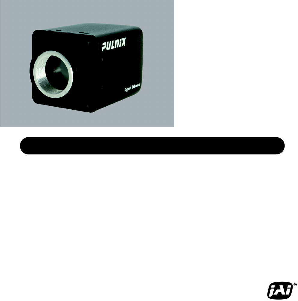
10394Rev. ASee the PossibilitiesOperation Manual TM/TMC-4200GE Progressive Scan Cameras
Page xList of FiguresFIGURE 48. Please contact JAI Inc. for password access. The password allows access to the EEPROM to rewrite factory default setti
Page xiList of TablesList of TablesTABLE 1. Hirose Connector, Pin Assignment . . . . . . . . . . . . . . . . . . . . . . . . . . . . . . . . . . . .
Page xiiList of Tables
Page 1TM-4200GE SoftwareSoftware IntroductionTM-4200GE SoftwareOperation Manual1 Software Introduction1.1 Scope of the DocumentThis manual describes h
Page 2TM-4200GE SoftwareSoftware IntroductionNote: Refer to the section on time-outs and packets in the Cam2Net User’s Manual for more information on
Page 3TM-4200GE SoftwareSoftware IntroductionFIGURE 1. Scanning for Drivers4. The Driver Installation Tool dialog box appears with a listing of all NI
Page 4TM-4200GE SoftwareSoftware Introduction3. Click the Change or Remove button as shown in Figure 3 on page 4.FIGURE 3. Change and Remove Buttons1.
Page 5TM-4200GE SoftwareSoftware IntroductionFIGURE 5. Select Camera Window5.Go to the Acquisition tab and click Start. An image stream should appear.
Page 6TM-4200GE SoftwareConnectors2 ConnectorsThe camera has two sockets, as shown in Figure 6 below:• 12-pin Hirose for power, trigger, RS-232 commun
Page 7TM-4200GE SoftwareConnectorsFIGURE 7. HR10A-10R-12P2.2 EthernetThe GigE socket, marked on the camera’s back panel as GigE, is a standard RJ-45 E
Page ii
Page 8TM-4200GE SoftwareConfiguring the TM-4200GE Camera3 Configuring the TM-4200GE CameraThe configuration of the GigE camera consists of two parts:
Page 9TM-4200GE SoftwareConfiguring the TM-4200GE CameraTo use the integrated GigE camera software, follow these steps: 1. Start the Camera Interface
Page 10TM-4200GE SoftwareConfiguring the TM-4200GE Camera3.2 Configuring the ImagerTo configure the TM-4200GE’s imager, use the integrated GigE camera
Page 11TM-4200GE SoftwareConfiguring the TM-4200GE Camera3.2.1 GUI FeaturesYou can control the following camera functions using the integrated camera
Page 12TM-4200GE SoftwareConfiguring the TM-4200GE CameraFIGURE 12. Advanced Configuration - Port Communication3.4.2 Exposure Control In Exposure Cont
Page 13TM-4200GE SoftwareConfiguring the TM-4200GE Camera Shutter ModeThe exposure control has two different settings. Select the desired setting usin
Page 14TM-4200GE SoftwareConfiguring the TM-4200GE Camera3.4.3 Scan ModeThe TM-4200GE camera has full and partial scan modes as shown in Figure 16. Th
Page 15TM-4200GE SoftwareConfiguring the TM-4200GE CameraFIGURE 17. Programmable Scan Set Dialog Box. Enter the total number of lines desired in the s
Page 16TM-4200GE SoftwareConfiguring the TM-4200GE Camera3.4.6 Gain Settings3.4.6 (a) GainThe Gain Settings control box, shown in Figure , allows y
Page 17TM-4200GE SoftwareConfiguring the TM-4200GE CameraFIGURE 19. Offset Level. 3.4.8 Look-Up TableThe look-up table (LUT) control, shown in Figure
Page iiiNoticeThe material contained in this manual consists of information that is proprietary to JAI Inc., and may only be used by the pur-chasers o
Page 18TM-4200GE SoftwareConfiguring the TM-4200GE CameraFIGURE 21. Memory Pages To reset memory page 1 to the factory default settings, load memory p
Page 19TM-4200GE SoftwareConfiguring the TM-4200GE Camera3.4.13 Save/Restore Settings to Your Hard DiskTo save your current settings into the XML file
Page 20TM-4200GE SoftwareConfiguring the TM-4200GE Camera3.4.15 Main Menu: “Option”3.4.15 (a) Test PatternThe Grabber Settings tabbed dialog box ha
Page 21TM-4200GE SoftwareSignal Handling4 Signal HandlingThis section briefly describes the signal handling of the GE cameras in the following section
Page 22TM-4200GE SoftwareSignal HandlingFIGURE 23. GE Camera GPIO Control BlockInputs I0 through I7 can be either external or internal inputs to the l
Page 23TM-4200GE SoftwareSignal HandlingFIGURE 24. GPIO Look-Up TableQ0 = I4
Page 24TM-4200GE SoftwareSignal HandlingFIGURE 25. The GPIO Configuration4.4 GPIO Label TableTable 2 shows which GPIO inputs carry the different sign
Page 25TM-4200GE SoftwareSignal HandlingTable 3 shows which output labels carry the output signals.TABLE 3. GPIO Look-Up Table Output Labels4.5 Pulse
Page 26TM-4200GE SoftwareSignal HandlingGranularity = 1Now check the Periodic option and change the camera settings to Async 9. This triggers the came
Page 27TM-4200GE SoftwareGigE Series Camera Serial Commands5 GigE Series Camera Serial CommandsYou can control the GigE series cameras by serial comma
Page iv
Page 28TM-4200GE SoftwareGigE Series Camera Serial CommandsCommand ParameterEnd of Cmd Ack. Response DescriptionLookup Table:LINR <cr> :o<cr&
Page 29TM-4200GE SoftwareGigE Series Camera Serial CommandsTABLE 5. Command ResponsesCommand ParameterEnd of Cmd Ack. Response DescriptionMiscellaneou
Page 30TM-4200GE SoftwareGigE Series Camera Serial CommandsBit 2 Shutter 20000=Async no shutter 0001 - 1000=Async preset shutters 1-8Bit 3 Shutter
January 31, 2007Dual-Tap TM-4200GE AccuPiXEL Series Camera-Control SoftwareDual-Tap TM-4200GE AccuPiXEL Series Camera-Control SoftwareOperation Manual
Page 32Dual-Tap TM-4200GE AccuPiXEL Series Camera-Control SoftwareIntroduction6.1 Software InstallationFollowing are the instructions to install the D
Page 33Dual-Tap TM-4200GE AccuPiXEL Series Camera-Control SoftwareIntroductionFIGURE 28. AccuPIXel Setup screen6.1.3 Uninstalling the SoftwareTo unins
Page 34Dual-Tap TM-4200GE AccuPiXEL Series Camera-Control SoftwareIntroductionFIGURE 29. The “Add or Remove Programs” utility can uninstall older soft
Page 35Dual-Tap TM-4200GE AccuPiXEL Series Camera-Control SoftwareIntroduction6.4 GUI FeaturesThe following is a list of camera functions that PC seri
Page 36Dual-Tap TM-4200GE AccuPiXEL Series Camera-Control SoftwareIntroduction6.5 Operating The Control Software6.5.1 Exposure Control The TM-4200GE e
Page 37Dual-Tap TM-4200GE AccuPiXEL Series Camera-Control SoftwareIntroductionFIGURE 33.Trigger mode uses a manual or sensor command to open and close
Page vTable of ContentsTable of Contents1 Software Introduction . . . . . . . . . . . . . . . . . . . . . . . . . . . . . . . . 11.1 Scope of the Docu
Page 38Dual-Tap TM-4200GE AccuPiXEL Series Camera-Control SoftwareIntroduction6.5.1 (c) Scan AreaChanging the scan area affects the image resolutio
Page 39Dual-Tap TM-4200GE AccuPiXEL Series Camera-Control SoftwareIntroductionFIGURE 37. Click the Apply button once the desired scan is programmed.6.
Page 40Dual-Tap TM-4200GE AccuPiXEL Series Camera-Control SoftwareIntroductionFIGURE 39. The R Auto Offset box is checked only while the command is be
Page 41Dual-Tap TM-4200GE AccuPiXEL Series Camera-Control SoftwareIntroductionFIGURE 43. Image Pre-Processing is activated by checking “Enable Blemis
Page 42Dual-Tap TM-4200GE AccuPiXEL Series Camera-Control SoftwareIntroductionThe Gamma.45 option is designed to cause the camera to gather light for
Page 43Dual-Tap TM-4200GE AccuPiXEL Series Camera-Control SoftwareIntroduction6.5.6 Main Menu: “Option”6.5.6 (a) PasswordFIGURE 48. Please contact
Page 44Dual-Tap TM-4200GE AccuPiXEL Series Camera-Control SoftwareIntroduction
Page 45TM-4200GE HardwareHardware IntroductionTM-4200GE HardwareOperation Manual7 Hardware Introduction7.1 Product DescriptionThe JAI Inc. TM-4200GE s
Page 46TM-4200GE HardwareHardware Introduction7.2 Features• Small size and light weightThe printed circuit boards in the TM-4200GE have been arranged
Page 47TM-4200GE HardwareInstallation8 InstallationThe following instructions are provided to help you to set up your camera. We suggest that you read
Page viTable of Contents6 Introduction . . . . . . . . . . . . . . . . . . . . . . . . . . . . . . . . . . . . . . 316.1 Software Installation . . .
Page 48TM-4200GE HardwareInstallation8.2 Camera Setup8.2.1 Heat DissipationThe TM-4200GE is a compact 2k by 2k camera. Since all the electronics have
Page 49TM-4200GE HardwareInstallation8.2.2 (b) Ethernet ConnectorThe GigE socket, marked on the camera’s back panel as GigE, is a standard RJ-45 Et
Page 50TM-4200GE HardwareInstallation8.2.3 (b) JAI Inc. Power CablesIf you are using JAI Inc. power cables such as the 12P-02S, please refer to the
Page 51TM-4200GE HardwareInstallation8.2.4 Attaching the Camera LensThe TM-4200GE camera accepts 1.2-inch or larger format size C-mount lenses. To att
Page 52TM-4200GE HardwareOperation9 Operation9.1 Progressive ScanningStandard TV-system scanning is 525 lines interlace scanning as specified in the R
Page 53TM-4200GE HardwareOperation9.1.2 Programmable Scan AreaIn Programmable Scan Area Mode, users can specify both the start point of the active sca
Page 54TM-4200GE HardwareOperationFIGURE 53. Bayer 1FIGURE 54. Bayer 29.1.3 Full Scan Area 2x2 BinningTM/TMC-4200 CL has a 2x2 binning of the full sc
Page 55TM-4200GE HardwareOperationFIGURE 55. 2x2 Binning9.1.4 Sub-sampling Digital ZoomTM/TMC-4200CL has four sub-sampling digital zoom modes:1x, 2x,
Page 56TM-4200GE HardwareOperationFIGURE 56. Sub-sampling Digital ZoomFIGURE 57. Sub-sampling Digital Zoom 2x
Page 57TM-4200GE HardwareOperationFIGURE 58. Sub-sampling Digital Zoom 3x
Page viiTable of Contents9.3.2 Programmable Exposure-Continuous Mode . . . . . . . . . . . . . . . . . . . . . . . . . 649.3.3 Asynchronous No Shutter
Page 58TM-4200GE HardwareOperationFIGURE 59. Sub-sampling Digital Zoom 4xTABLE 7. Scan Area Start Points9.2 Bayer Color Filter (Color Versions)JAI Inc
Page 59TM-4200GE HardwareOperation9.2.1 Color Filter ArrayJAI Inc. AccuPiXEL cameras use Bayer CFA (color filter array) as their standard primary colo
Page 60TM-4200GE HardwareOperation9.2.3 Starting Pixel ConfigurationAll manufacturers produce identical Bayer CFAs, but there are slight differences b
Page 61TM-4200GE HardwareOperationFIGURE 62. Example of TMC-4200GE (Same as TM-4200GE)9.2.5 Camera FunctionsAccuPiXEL color cameras perform all functi
Page 62TM-4200GE HardwareOperation9.2.6 Timing ChartFIGURE 63. TM-4200GE Timing ChartScan ModeABCDUT ZtBdualsingle130023921300239213002392130023921300
Page 63TM-4200GE HardwareOperation9.2.7 Interpolation SoftwareThe color interpolation can be performed in the frame grabber or by using the host compu
Page 64TM-4200GE HardwareOperation9.3.1 Preset ShutterTABLE 8. Electronic Preset Shutter9.3.2 Programmable Exposure-Continuous ModeThe exposure time o
Page 65TM-4200GE HardwareOperationFIGURE 64. External Trigger Timing.9.3.4 Asynchronous Programmable Exposure ModeIn Asynchronous Programmable Exposur
Page 66TM-4200GE HardwareOperationFIGURE 65. Asynchronous Programmable External Trigger9.3.5 Pulse Width Control ModeIn Pulse Width Control (PWC) Mode
Page 67TM-4200GE HardwareOperationFIGURE 66. Pulse Width Control Trigger 9.3.6 Particle Imaging Velocimetry Fixed Exposure ModeIn Particle Imaging Vel
Page viiiTable of Contents
Page 68TM-4200GE HardwareOperation9.3.7 PWC PIV ModeThe PWC PIV is based on PIV Fixed Exposure. In this mode, the first time exposure is controlled by
Page 69TM-4200GE HardwareOperation9.4 Dynamic Range Control FIGURE 69. Output and BloomingThe typical interline transfer CCD has fixed noise levels ba
Page 70TM-4200GE HardwareOperation9.5 External Sync and Pixel LockingThe TM-4200CL accepts an external sync of standard HD and VD at TTL level for gen
Page 71TM-4200GE HardwareOperationFIGURE 71. Digital Data Output Order for ConfigurationFIGURE 72. Field Video Timing--Continuous ModeTABLE 10. Video
Page 72TM-4200GE HardwareOperationTABLE 11. External HD Locking and External VD ResetTABLE 12. Async ResetNote: s1=1s2=3s3=7s4=15s5=30s6=61s7=122s8=24
Page 73TM-4200GE HardwareTroubleshooting10 Troubleshooting10.1 Problems and SolutionsFollowing are troubleshooting tips for common problems. In genera
Page 74TM-4200GE HardwareTroubleshooting10.1.4 Symptom: Video does not Display ProperlyRemedies: Open the Coyote software and click on the Display hea
Page 75TM-4200GE HardwareAppendix11 Appendix11.1 SpecificationsTABLE 13. TM-4200GE Camera Specifications TableFeature TM-4200GEImager 1.2" progre
Page 76TM-4200GE HardwareAppendix11.1.1 TM-4200GE Physical DimensionsFIGURE 73. Physical DimensionsGigEPOWER25.4 [1.00]1”– 3250.8 [2.00]25.4 [1.00]
Page 77TM-4200GE HardwareAppendix11.1.2 Spectral ResponseFIGURE 74. Spectral Response0.40.350.30.250.20.150.10.050400 450 500 550 600 650 700 750 800
Page ixList of FiguresList of FiguresFIGURE 1. Scanning for Drivers . . . . . . . . . . . . . . . . . . . . . . . . . . . . . . . . . . . . . . . . .
Page 78Appendix
www.jai.com
JAI Inc.625 River Oaks ParkwaySan Jose, CA 95134Tel: 408-383-0300Tel: 800-445-5444Fax: 408-383-0301 www.jai.comSee the Possibilities10394Rev. AEmai
© 2020, manymanuals.com. All rights reserved. | 0.559 s |
 Manymanuals.com
 Manymanuals.de
 Manymanuals.fr
 Manymanuals.it
 Manymanuals.pl
 Manymanuals.cz
 Manymanuals.es
 Manymanuals-pt.com
Comments to this Manuals